
ENGINEERING CAPABILITIES
Advanced RF & Microwave Engineering Capabilities
From custom RF modules to integrated microwave subsystems, AWG Tech provides practical engineering solutions for demanding RF applications.
With over 20 years of hands-on experience, our expertise covers RF architecture, component integration, prototype development, measurement, verification and troubleshooting.
OUR ENGINEERING APPROACH
From RF Architecture to Integrated Hardware
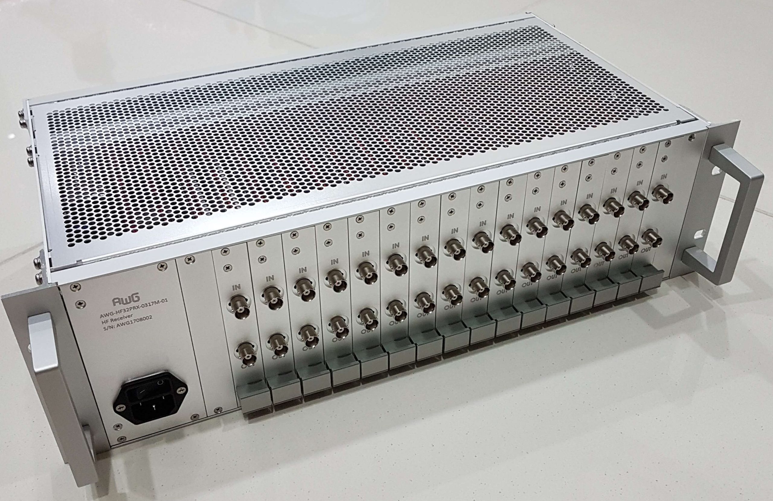
AWG Tech combines practical RF engineering experience with system-level integration capabilities to develop solutions tailored to specific application requirements.
Our work extends beyond component selection. We consider the complete RF signal chain, including gain distribution, noise figure, linearity, filtering, isolation, impedance matching, power handling and thermal management.
From initial requirements and RF architecture through prototype integration, troubleshooting and performance verification, we focus on delivering solutions that work reliably in real-world operating conditions.
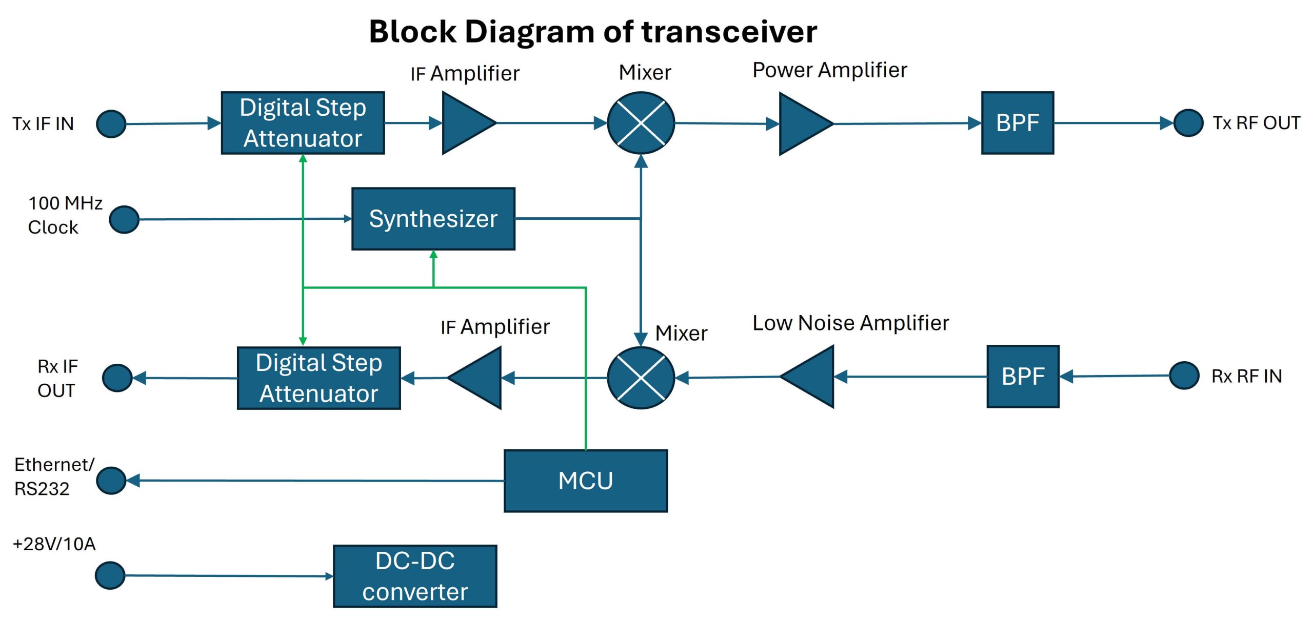
Figure 1. Illustrative RF transceiver architecture showing transmit and receive signal chains, frequency synthesis, digital attenuation, system control and power conversion. Actual implementations vary according to operating frequency, output power, noise figure, linearity and application requiremen
Engineering Beyond Individual RF Components
Designing an RF subsystem requires more than selecting components that meet individual specifications. The interaction between filters, amplifiers, mixers, attenuators and interconnections determines overall system performance.
For example, receiver noise figure depends on the gain and noise contribution of successive stages, while transmitter performance requires careful consideration of output power, linearity, unwanted signals and thermal dissipation.
AWG Tech considers these system-level trade-offs during architecture development, integration and verification to help achieve the required performance under practical operating conditions
WHAT WE DO
Our RF & Microwave Engineering Capabilities
Practical engineering expertise spanning RF design, subsystem integration, custom assemblies and performance verification.
Custom Transceivers
Transmit and receive architectures, frequency conversion and signal conditioning.
Learn More →
RF System Integration
Integration of RF modules, control electronics, power distribution and mechanical assemblies.
Learn More →
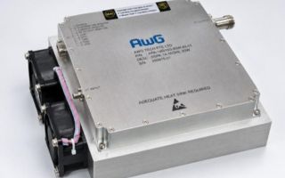
High-Power RF Systems
Amplifier integration, pulsed RF operation, power handling and thermal management.
Learn More →
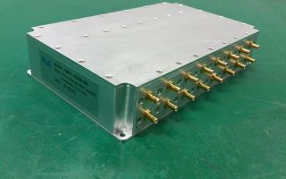
Custom RF Modules & Assemblies
Custom filters, switched filter banks, digital step attenuators, RF distribution networks and application-specific microwave assemblies.
Learn More →
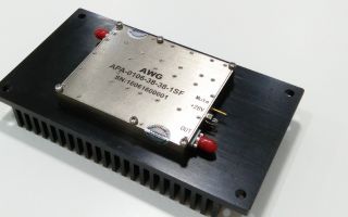
RF & Microwave Design Engineering Services
RF architecture, frequency conversion, impedance matching, gain distribution, filtering and signal-chain optimisation.
Learn More →
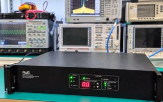
RF Measurement & Verification
RF performance characterisation, gain and noise figure measurements, linearity testing, troubleshooting and system verification.
Learn More →
CUSTOM ENGINEERING SOLUTIONS
Customed 4-Channel Switched Filter Bank: Solving RF Isolation Challenges
A practical example of how RF switching topology, filter selection and signal-path balancing influence subsystem performance.
The Engineering Challenge
AWG Tech developed a custom four-channel switched filter bank covering 1.25–4.0 GHz for an application requiring high isolation, fast switching and consistent insertion loss across multiple frequency bands.
The design requirements included:
-
Frequency coverage from 1.25 to 4.0 GHz
-
Four overlapping filter channels
-
Minimum 500 MHz bandwidth per channel
-
Minimum 250 MHz overlap between adjacent channels
-
At least 60 dB inter-port isolation
-
Switching time of less than 100 µs
-
Second-harmonic suppression and specified out-of-band rejection
The design required each filter channel to provide at least 500 MHz of signal bandwidth, with a minimum overlap of 250 MHz between adjacent channels. In addition to second-harmonic suppression and stopband rejection requirements, the switching network needed to provide at least 60 dB isolation between ports.
Why Conventional RF Switching Design Was Insufficient
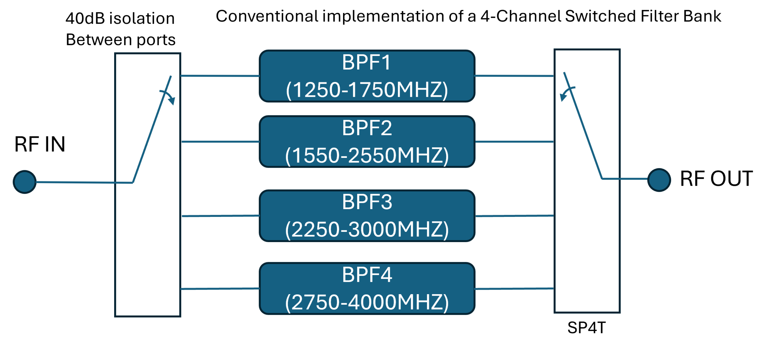
A conventional switched filter bank typically uses RF switches to select the required filter path.
However, many surface-mount RF switching ICs provide isolation of approximately 40 dB across a broad frequency range. In this application, that level of isolation was insufficient.
The overlapping filter passbands made the problem more challenging. Where two filters pass some of the same frequencies, filter rejection cannot necessarily compensate for leakage through the switching network.
AWG's Engineering Approach
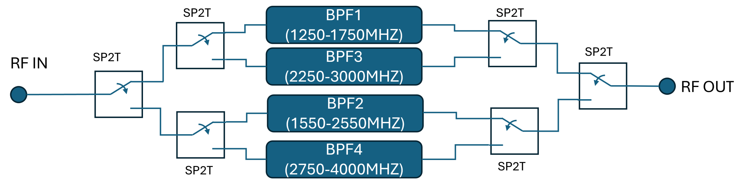
To address this challenge, AWG developed a hierarchical switching arrangement using SPDT switches rather than a conventional SP4T topology.
The design separated filter paths within the switching network to address leakage between overlapping channels.
Additional design considerations included:
- Switching Architecture: The switching network was arranged to provide additional isolation between filter paths, particularly where adjacent filter passbands overlapped. This addressed the limitations of a conventional switching arrangement.
- Low-loss cavity filters: Selected for their low insertion loss and high frequency selectivity.
- Fast Switching Speed: Pin diode RF switches (instead of mechanical RF switches) were selected to provide the required switching speed.
- Signal-path balancing: Small attenuators of 1-2dB were incorporated into individual paths to balance the overall insertion loss.
- Frequency planning: Four overlapping filter channels were selected to cover the required frequency range.
- System integration: Switching topology and filter characteristics were considered together rather than as independent components.
Engineering Lessons
This project illustrates why RF subsystem performance cannot always be predicted from individual component datasheets.
In a switched filter bank, filter rejection, switch isolation, channel overlap and insertion loss interact to determine overall performance.
For demanding RF applications, the choice of switching architecture can be just as important as the selection of the filters themselves.
Engineering Insight — Optimising the Complete RF Signal Path
Improving one RF performance parameter can introduce trade-offs elsewhere.
For example, additional switching stages can improve isolation but may increase insertion loss. Likewise, adding attenuation to equalise channel losses deliberately sacrifices a small amount of signal power to achieve more consistent transmission characteristics.
The engineering objective is therefore not necessarily to minimise every individual loss, but to achieve the required overall system performance.
ENGINEERING VERIFICATION
RF Measurement, Testing & Performance Verification
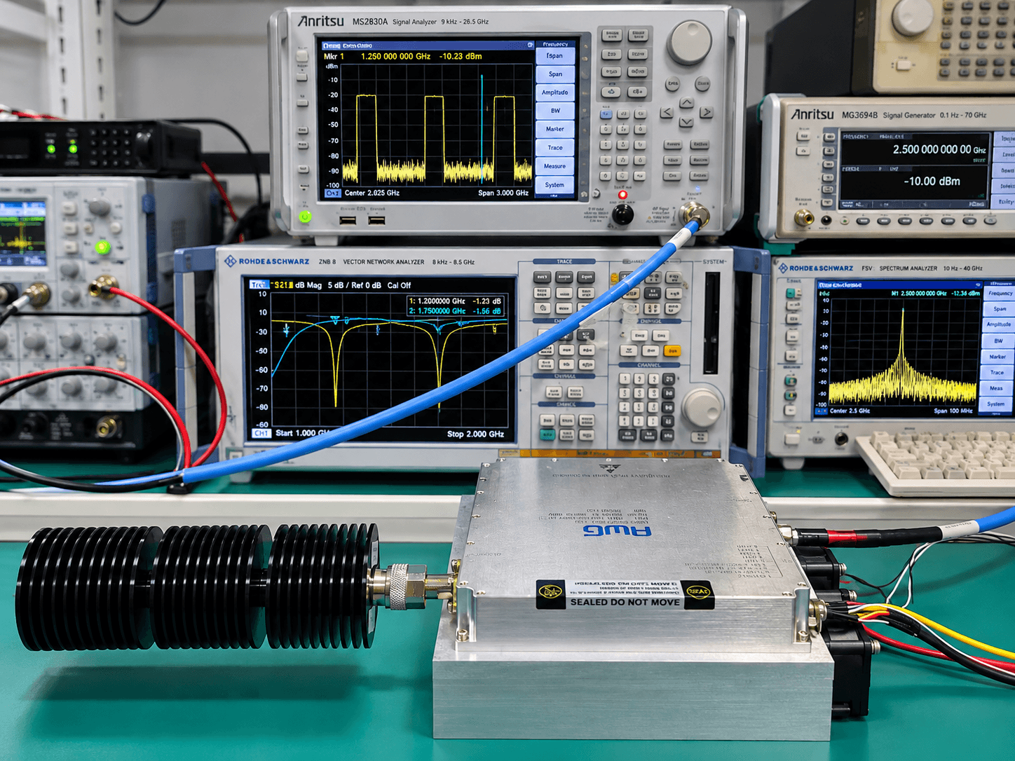
AWG Tech provides RF measurement, performance characterisation and system-level verification throughout the development and integration process. Our in-house capabilities cover RF measurements, troubleshooting and functional testing, while environmental and EMC qualification testing is coordinated through external accredited laboratories.
RF subsystem performance depends on how individual components interact within the complete signal chain. Gain distribution, impedance mismatch, switching isolation, noise figure and thermal conditions can all influence system performance.
AWG Tech combines RF measurement and practical troubleshooting experience to identify integration issues, characterise subsystem performance and verify compliance with project-specific electrical requirements.
Your content goes here. Edit or remove this text inline or in the module Content settings. You can also style every aspect of this content in the module Design settings and even apply custom CSS to this text in the module Advanced settings.
S-Parameter & Network Measurements
Insertion loss, return loss, isolation, frequency response and impedance matching using vector network analysis.
RF Power & Signal Characterisation
Gain, output power, compression behaviour, harmonics, spurious signals and spectral performance.
Receiver & Subsystem Performance
Noise figure, gain distribution, signal-path isolation, switching behaviour and receiver-chain verification.
Environmental & Reliability Verification
Thermal evaluation, functional checks and coordination of environmental and EMC testing where required.
Engineering Insight — Why System-Level Verification Matter
An RF subsystem can contain components that individually meet their specifications yet still fail to achieve the required overall performance.
For example, insertion losses ahead of a low-noise amplifier can degrade receiver noise figure, while impedance mismatch between cascaded components can introduce gain ripple. In high-power RF assemblies, thermal conditions may also affect output power and stability.
System-level measurements are therefore essential for understanding the behaviour of the complete signal chain.
Environmental & EMC Qualification Support
AWG Tech has supported RF subsystem projects involving environmental and EMC testing against requirements drawn from MIL-STD-810, MIL-STD-461 and applicable commercial EMC standards, including FCC Part 15 Subpart B, EN 55032 and EN 55035.
Testing is performed through external laboratories, with the applicable standards, test methods and acceptance criteria determined by each project's requirements.
Depending on project requirements, testing may include temperature cycling, vibration, mechanical shock, conducted emissions, radiated emissions and immunity testing.
Our engineering involvement includes test planning, preparation, coordination, technical review of results and troubleshooting when necessary