
From System Specification to Qualified Hardware: Engaging AWG Tech for Custom Microwave Subsystems, Modules and Components
A turnkey guide to moving from high-level link budgets to flight- and field-ready RF hardware.
1. Bridging the Gap: Architecture to Hardware
When high-frequency programs fail to meet performance milestones, the root cause is rarely an isolated semiconductor or discrete filter. Most often, failures stem from cascaded interface penalties: unintended parasitic resonances between multi-vendor blocks, cumulative VSWR degradation, excessive inter-stage thermal loading, and microphonic phase noise under vibration.
Standard off-the-shelf catalog blocks offer convenience during early bench prototyping, but they introduce severe penalties in size, weight, power, and cost (SWaP-C) for operational deployments.
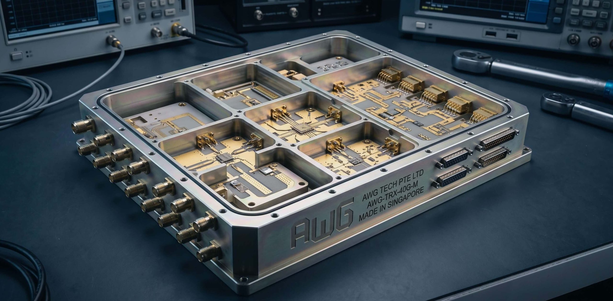
At AWG Tech, our systems engineering team acts as an extension of your own RF design and architecture group. Operating from Singapore’s high-precision manufacturing base, we design, simulate, assemble, and environmentally qualify integrated microwave front-ends, agile transceivers, and pulsed high-power assemblies operating up to 40 GHz.
Whether you require a custom form-factor replacement for a legacy defense assembly or are launching a new satellite payload, here is how our technical engagement pipeline operates.
2. What to Prepare: Key Parameters for an Initial SOW
You do not need a completed, frozen schematic to start working with AWG Tech. Our team regularly assists clients in translating high-level mission requirements into actionable subsystem specifications.
To help us conduct an initial link-budget and form-factor feasibility review, the following baseline parameters are most helpful:
-
Frequency Range & Operating Bandwidth: Exact passbands, intermediate frequencies (IF), and tuning resolution (e.g., X-band 8.5–10.5 GHz, 500 MHz instantaneous IF).
-
Cascaded Noise & Linearity Budgets: Target receiver noise figure (NF), input/output third-order intercept points (IIP3/OIP3), and dynamic range constraints.
-
Power Output & Duty Cycle: For transmit chains and solid-state power amplifiers (SSPAs), specify continuous wave (CW) or pulsed requirements (pulse width, PRF, and maximum duty cycle).
-
Channel Coherence: For phased-array radar or direction-finding (DF) systems, specify required channel-to-channel phase tracking (e.g., < ±2°) and amplitude matching (e.g., < ±0.5 dB).
-
Physical & Environmental Boundaries: Target form factor (chassis footprint, 1U–3U rackmount, or custom bathtub envelope), prime power supply limits (e.g., MIL-STD-704 compliance), and thermal/vibration operational envelopes (MIL-STD-810).
3. Our 4-Stage Execution Methodology
Every custom subsystem project follows a structured engineering workflow to compress schedule risk while maintaining baseline fidelity:
-
Phase 1: Architecture & Feasibility Review (1–2 Weeks)
We evaluate your preliminary requirements against physical component boundaries. We map out frequency conversion schemes, calculate spurious-free dynamic range (SFDR), evaluate cascaded noise factor, and identify potential packaging choke points.
-
Phase 2: Detailed Design & analysis (3–4 Weeks)
We will do a detailed study and analysis which may include advanced 3D electromagnetic (EM) modeling, non-linear circuit simulation, and thermal computational fluid dynamics (CFD). That way, we are able to reduce or eliminate design errors and parasitic coupling or verify heat dissipation pathways in GaN stages prior to cutting metal.
-
Phase 3: Prototype Fabrication & First Article Testing (FAT)
Housings are CNC-machined from aluminum 6061-T6 and surfaced with clear chromate conversion (MIL-DTL-5541) or gold plating. Sub-assemblies are populated in company approved surface-mount lines. Testing is conducted using vector network analyzers (VNAs), spectrum analyzers, and noise-figure meters calibrated to 40 GHz.
-
Phase 4: Environmental Screening & Build-to-Spec Delivery
Where required, prototypes may undergo operational burn-in and thermal cycling from -40°C to +85°C to verify phase stability and gain flatness before final qualification documentation and delivery.
4. Engineering Heritage & Certified Manufacturing Rigor
Executing high-frequency microwave designs demands more than simulation models—it requires deep physical fabrication experience and zero-defect workmanship. At AWG Tech, our engineering and assembly capabilities are backed by decades of direct hands-on experience designing, packaging, and qualifying mission-critical RF hardware for high-reliability applications.
Certified Assembly & Workmanship Standards
To guarantee long-term operational reliability in mission-critical environments, all precision assembly, soldering, and harness routing are executed by certified technical personnel adhering to international aerospace and defense benchmarks:
- IPC-A-610 Certified Personnel (Acceptability of Electronic Assemblies): Precision surface-mount (SMD) assembly, microelectronic die attach, and gold ribbon/wire bonding carried out under strict Class 2 (or Class 3) high-reliability electronics criteria.
- IPC/WHMA-A-620 Certified Personnel (Requirements & Acceptance for Cable & Wire Harness Assemblies): Precision routing, semi-rigid and flexible microwave coaxial harness termination, phase-matched cabling, and multi-pin micro-D interconnects assembled to high-performance defense standards.
- Traceable Vector Network & Spectral Verification: Every assembled module undergoes multi-point characterization using laboratory-grade vector network analyzers (VNAs), noise figure meters, and spectrum analyzers calibrated for traceability.
5. Frequently Asked Questions (FAQ)
Can AWG Tech handle "Build-to-Print" as well as "Build-to-Spec"?
Yes. While our primary focus is turnkey engineering ("Build-to-Spec" starting from system architecture), we also manufacture existing customer-designed microwave modules ("Build-to-Print"), providing assembly, precision microstrip tuning, and qualification.
What is the typical turnaround time for a custom prototype?
Depending on the complexity of the frequency plan and component lead times, initial functional prototypes are typically completed within 12 to 18 weeks following Critical Design Review (CDR) sign-off.
How do we initiate a mutual NDA?
You can request our standard corporate bilateral NDA directly via our technical intake form below, or send your organization’s standard mutual NDA template to sales@awg.com.sg. Our legal and technical team typically returns executed agreements within 24–48 hours.
6. Contact & Direct Engineering Channels
-
Engineering Headquarters: AWG Tech Pte Ltd, Singapore
-
Technical Consultation:
sales@awg.com.sg -
Direct Engineering Line:
+65 9763 7032 -
Operating Hours: 09:00 – 18:00 (SGT / UTC+8), Monday through Friday