
RF ENGINEERING SOLUTIONS
Custom RF Modules & Assemblies
AWG develops application-specific RF & Microwave modules that integrate filtering, amplification, switching and signal distribution into practical, testable assemblies.
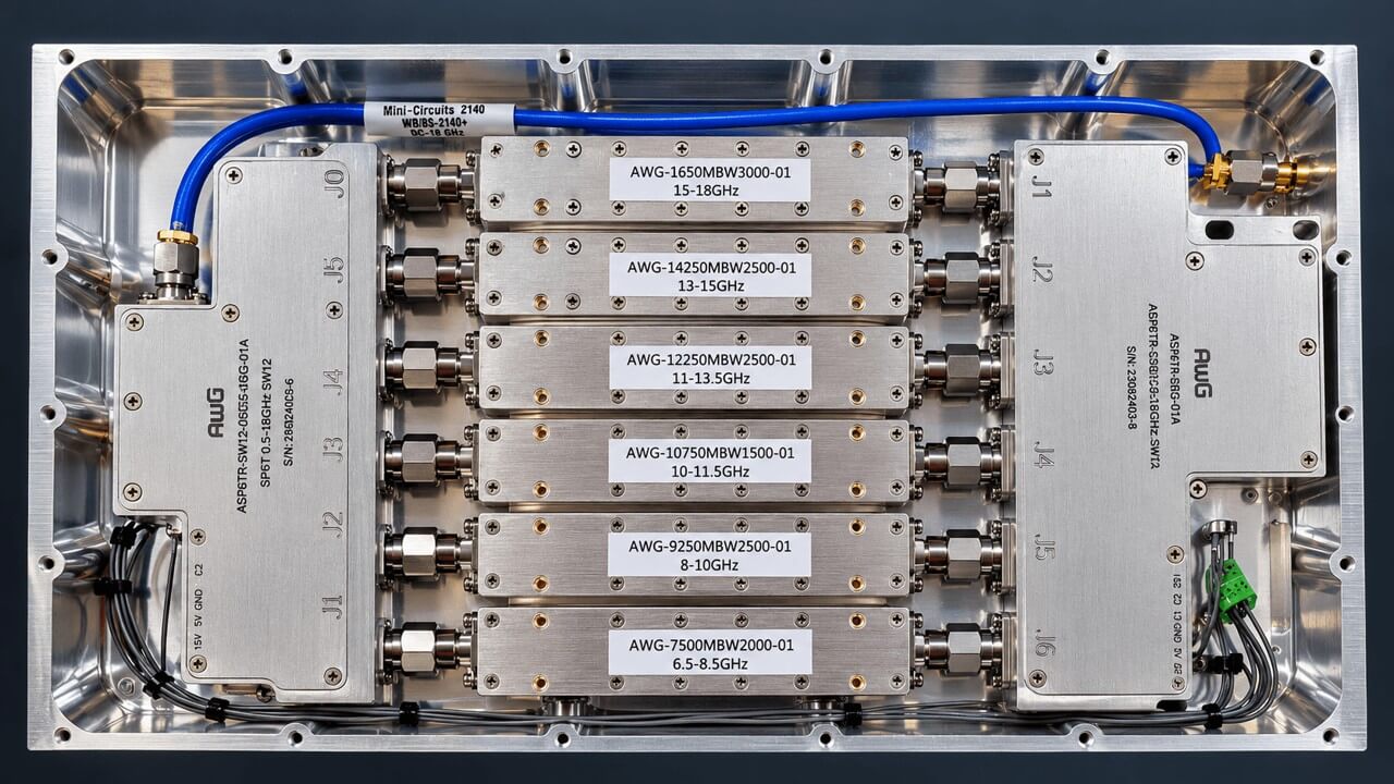
Custom RF Engineering Solutions
Beyond Standard RF Components
Off-the-shelf RF components are suitable for many applications. However, system-level requirements often call for a combination of functions that cannot be achieved efficiently using individual catalogue products.
A receiver front end, for example, may require several bandpass filters, RF switches, low-noise amplifiers and attenuators operating together under a common control interface.
Similarly, a signal distribution assembly may need to integrate power dividers, directional couplers, amplification and monitoring functions within a compact mechanical enclosure.
AWG Tech helps bridge the gap between individual RF components and complete RF systems.
Our custom module development approach considers:
-
RF performance: Frequency coverage, insertion loss, gain, return loss, isolation, noise figure, linearity and power handling.
-
Functional integration: Combining filtering, switching, attenuation, amplification and signal distribution.
-
Control interfaces: Digital control, switching logic, power management and system interfacing.
-
Mechanical requirements: Enclosure dimensions, RF connector placement, shielding, thermal management and mounting.
-
Verification: RF measurements, functional testing and environmental qualification where required.
The objective is to develop an RF assembly that meets the application's overall requirements, rather than optimising individual components in isolation.
Types of Custom RF Modules & Assemblies
AWG Tech develops application-specific RF and microwave modules by integrating filtering, amplification, attenuation, switching and signal distribution functions into practical assemblies.
Our solutions are developed around customer-defined electrical, mechanical and interface requirements, with consideration given to system performance, manufacturability and verification.
The following categories represent examples of custom RF modules and assemblies that AWG can support.
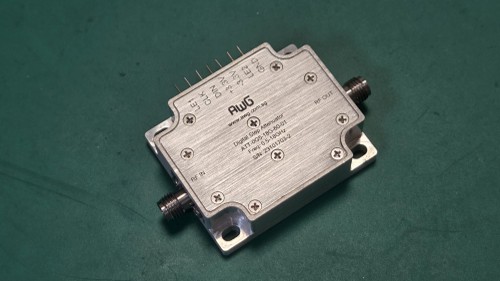
Digital Attenuator Modules
Programmable RF attenuation modules provide controlled signal-level adjustment for test systems, receiver front ends and automated RF equipment.
Engineering considerations: attenuation range, step resolution, insertion loss, switching speed, linearity and power handling.
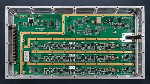
RF Power Distribution Assemblies
AWG Tech develops custom RF power distribution assemblies that integrate power dividers, amplifiers, directional couplers and frequency-selective filtering functions to meet application-specific signal distribution requirements.
Our engineering experience includes multi-channel RF assemblies incorporating three-way power splitting, amplification and bandpass filtering across different frequency bands.
Engineering considerations: amplitude balance, phase balance, insertion loss, isolation, directivity and power capacity.
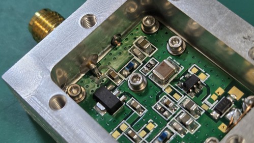
Amplifier & Receiver Front-End Modules
Integrated RF front ends combine amplification, filtering, attenuation and protection functions to condition signals before further processing.
Engineering considerations: noise figure, gain, linearity, dynamic range, stability and thermal performance.
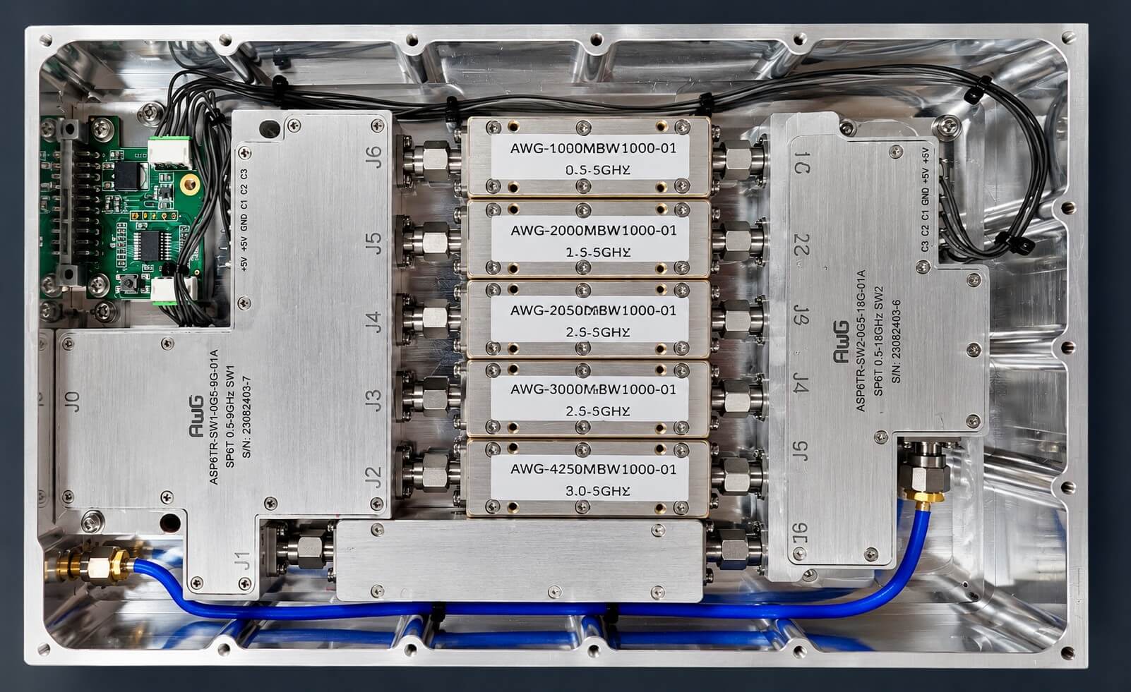
Switched Filter Banks & RF Preselectors
Multi-band filter assemblies combine bandpass filters and RF switching networks to provide selectable frequency coverage and out-of-band signal rejection.
Engineering considerations: passband coverage, insertion loss, rejection, switching isolation and control architecture.
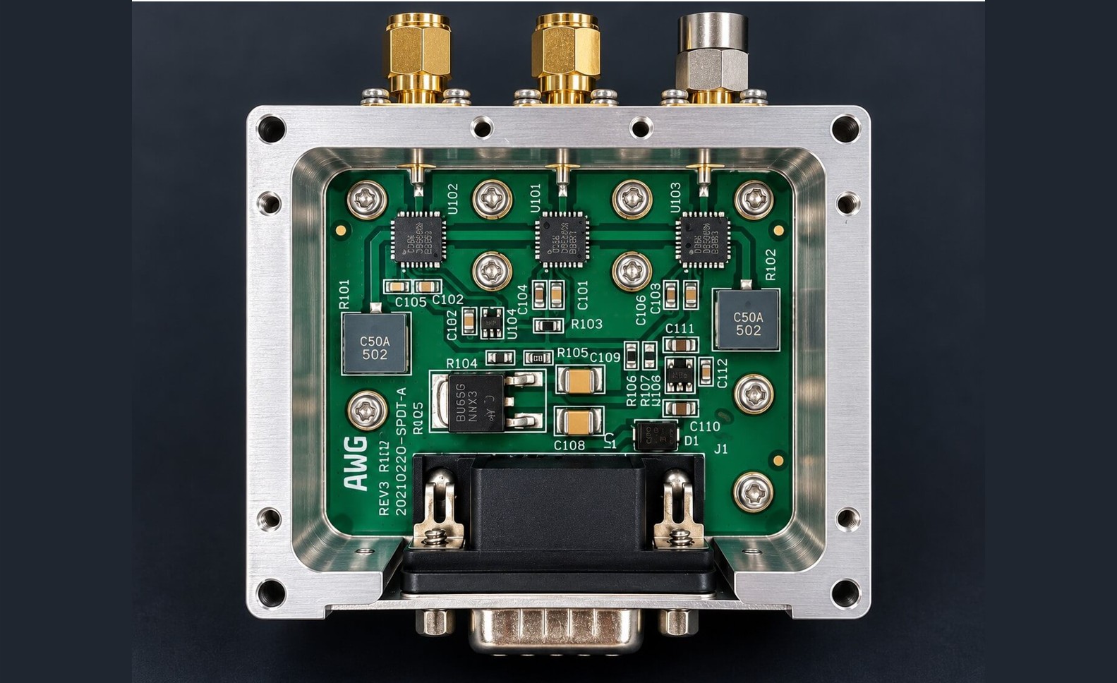
RF Switching Assemblies
AWG Tech develops custom RF switching modules and assemblies with integrated digital control interfaces, including RS485-controlled switching solutions.
These assemblies combine RF switching devices, control electronics, RF connectors and mechanical packaging into application-specific modules for automated test equipment, signal routing and integrated RF systems.
Engineering considerations: insertion loss, port isolation, switching time, power handling and control interfaces.
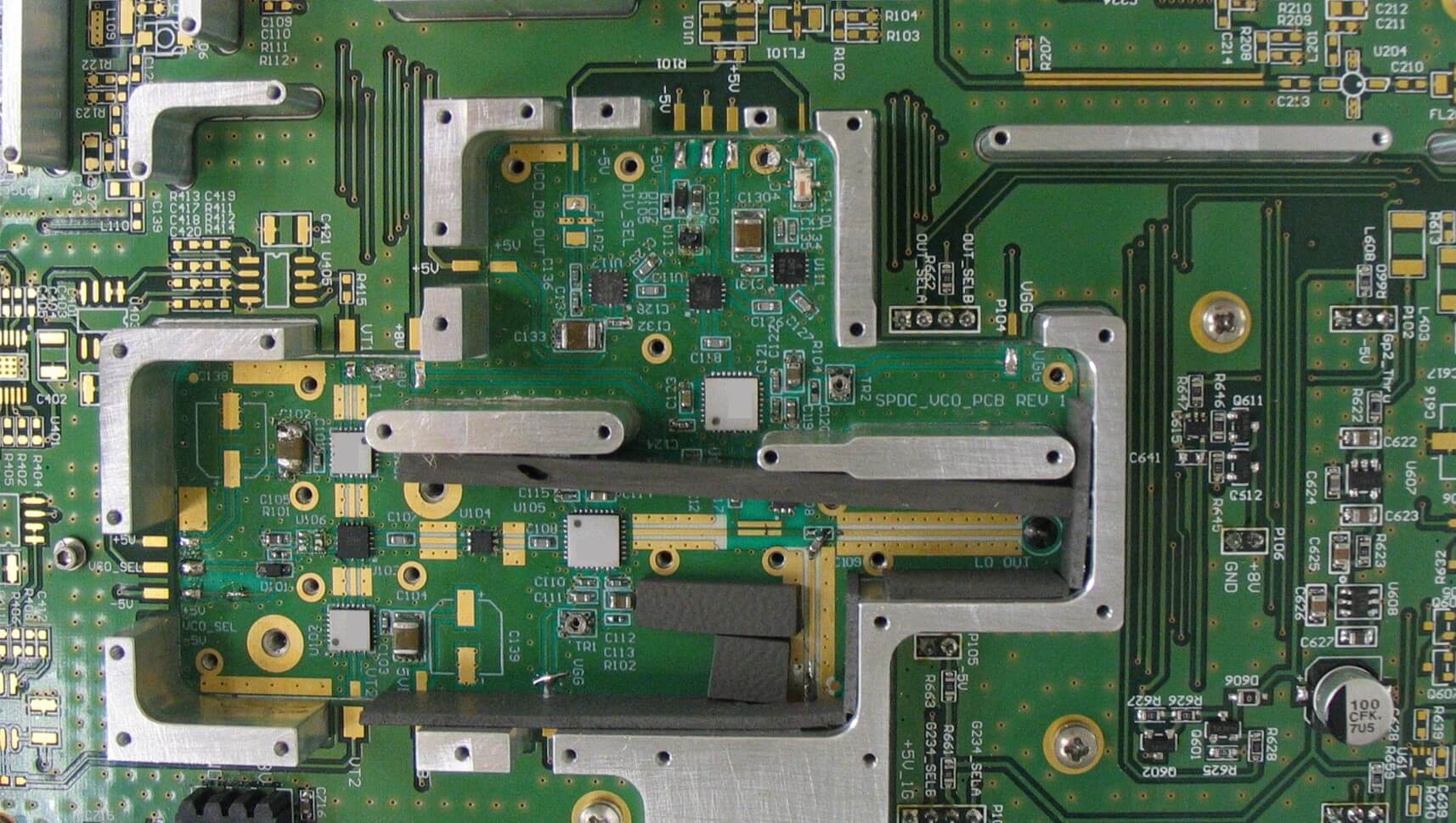
Application-Specific RF Assemblies
Multi-function RF assemblies integrate several signal-processing stages, control circuits and mechanical components into a single functional unit.
Engineering considerations: system architecture, interface compatibility, RF shielding, thermal design and verification.
RF Module Integration & Engineering Capabilities
Developing a custom RF module involves more than connecting individual components together. The electrical, mechanical and control interfaces must be considered as part of the overall system architecture.
AWG Tech supports the development of application-specific RF and microwave assemblies, combining RF components, control electronics and mechanical packaging into integrated functional modules.
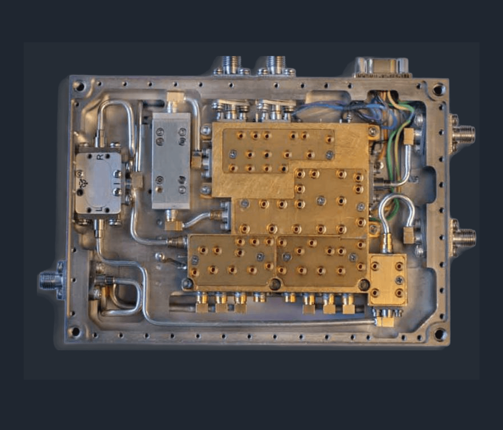
From Discrete RF Building Blocks to Integrated Assemblies
Developing mission-critical RF and microwave subsystems requires solving the complex interactions that occur when discrete active and passive devices are condensed into a single physical envelope. Parasitic substrate coupling, inter-stage VSWR mismatch, cavity resonances, and thermal dissipation cannot be resolved by standard catalog interconnects.
AWG Tech designs, packages, and manufactures application-specific RF and microwave assemblies (IMAs) from DC to 40 GHz. We bridge high-level system requirements with physical hardware execution—integrating front-end signal conditioning, agile frequency conversion, digital control, and ruggedized mechanical packaging into monolithic, qualified functional modules.
RF Architecture & Signal-Chain Co-Design
We engineer the entire cascaded signal path from the antenna or IF interface inward, optimizing system-level trade-offs before cutting metal:
-
Cascaded Link-Budget Optimization: Detailed modeling of cascaded Noise Figure (NF), input/output third-order intercept points (IIP3/OIP3), dynamic range, and Spurious-Free Dynamic Range (SFDR).
-
Multi-Octave Matching & Return Loss: Broadband impedance synthesis and transition design (microstrip, coplanar waveguide, stripline, and coaxial interfaces) to minimize ripple and phase distortion.
-
Isolation & Leakage Control: Achieving > 60–70 dB inter-channel isolation in dense multi-channel arrays, switched filter banks (SFBs), and directional sensing front-ends through strategic partitioning and multi-cavity isolation ribs.
Embedded Digital Control & Telemetry Interfaces
Modern RF front-ends require deterministic, microsecond-level digital control to support agile frequency hopping, dynamic attenuation, and high-speed T/R switching:
-
Standard Control Protocols: Native integration of embedded microcontrollers and CPLDs supporting SPI, I2C, UART, RS-422, RS-485, and Ethernet (SCPI/SNMP) for remote bus control.
-
Agile Switching & Fast Blanking: High-speed TTL driver integration achieving sub-microsecond state transitions for PIN diode/solid-state switches and step attenuators.
-
Autonomous System Telemetry: Built-in forward/reflected RF power detection, high-VSWR automated trip protection, current-draw monitoring, and onboard temperature sensors for real-time health and usage monitoring (HUMS).
Mechanical, Thermal & Environmental Packaging
Subsystem reliability is intrinsically tied to mechanical integrity and thermal equilibrium. Our packaging strategies are engineered to withstand demanding airborne, naval, and terrestrial environments:
-
Precision Bathtub Enclosures: Custom multi-cavity enclosures CNC-machined from aluminum 6061-T6 or dip-brazed brass, finished with clear chromate conversion (MIL-DTL-5541) or selective nickel/gold plating for optimal grounding and corrosion resistance.
-
Thermal Management for High-Duty Operations: Conduction, forced-air, or heat-spreader designs engineered via thermal CFD to keep GaN and GaAs junction temperatures within conservative derating envelopes.
-
Environmental Ruggedization: Structural design and sealing tailored to meet operational profiles aligned with MIL-STD-810 (shock, vibration, wide-temperature operation from -40°C to +85°C) and MIL-STD-461 for strict EMI/EMC shielding.
Featured Engineering Case Study
3-Band, 8-Channel Phase & Amplitude Matched UHF Receiver
Application: Multi-channel receiver system for an airborne application
AWG Tech developed a custom UHF receiver system comprising eight independent receiver modules, each supporting three selectable frequency bands.
A key requirement was to achieve closely matched amplitude and phase responses across all eight modules while maintaining the specified gain, noise figure, frequency selectivity and programmable attenuation performance.
The project involved RF architecture design, bandpass filter tuning, amplifier and attenuator integration, digital control and extensive RF measurements.
Project Requirements
The receiver modules were designed for three operating frequency bands:
Operating Bands
Frequency Range
Band 1
Band 2
Band 3
314–378 MHz
414–478 MHz
514–578 MHz
Key performance requirements included a minimum gain of 38 dB, a maximum noise figure of 6 dB at 0 dB attenuation, and 40 dB of programmable gain control in 1 dB steps.
Of particular importance were the channel-matching requirements: amplitude matching within ±0.5 dB and phase matching within ±8°.
RF Architecture & Implementation
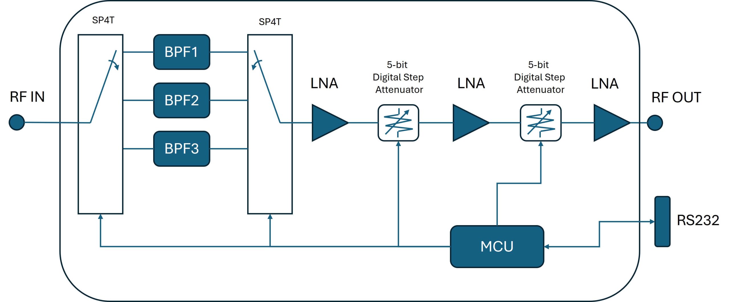
Each receiver module incorporates a switched bandpass filter bank, three cascaded amplifier stages, two digitally controlled attenuators and a microcontroller-based control system.
The incoming RF signal passes through the selected bandpass filter to suppress unwanted out-of-band signals before entering the amplifier and attenuation stages.
The amplifier stages provide the required receiver gain, while the programmable attenuators allow signal levels to be adjusted according to operating requirements.
The microcontroller manages frequency-band selection and attenuation settings through an RS232 control interface.
Eight receiver modules using this architecture were implemented to form the complete multi-channel receiver system.
The Engineering Challenge
Engineering Challenge — Achieving Amplitude & Phase Matching
One of the most demanding aspects of the project was achieving consistent amplitude and phase responses across eight independently manufactured receiver modules.
Although the modules shared the same RF architecture, differences in filter characteristics, component tolerances and RF interconnections introduced variations in the overall frequency response.
Each bandpass filter was carefully tuned for its amplitude and phase response before integration into the receiver.
However, the response of an individual filter can change when connected to RF switches, amplifiers and other circuit elements. Consequently, the filters required further tuning after integration into the complete receiver signal chain.
Amplitude and phase matching were evaluated using a vector network analyser (VNA), with one receiver module selected as the reference.
The VNA's mathematical functions were used to compare the responses of the remaining modules against the reference at corresponding frequencies across the operating bands.
This required repeated measurement, adjustment and verification to achieve the specified channel-to-channel matching.
The project illustrates an important principle of RF integration: meeting individual component specifications does not necessarily guarantee the required performance at the complete assembly level
Representative RF Test Results
The following measurements are representative results from Band 3 (514–578 MHz), the highest-frequency operating band.
Parameter
Reported Measured Performance
Gain
Gain Flatness
Noise Figure
Amplitude Matching
Phase Matching
43.0-43.4 dB
0.3-0.4dB
2.9-3.6dB
0.1-0.4dB
0-4.4°
The results demonstrate close channel-to-channel amplitude and phase matching, together with consistent gain and noise performance in the representative band.
Sample Plots (for Band 3)
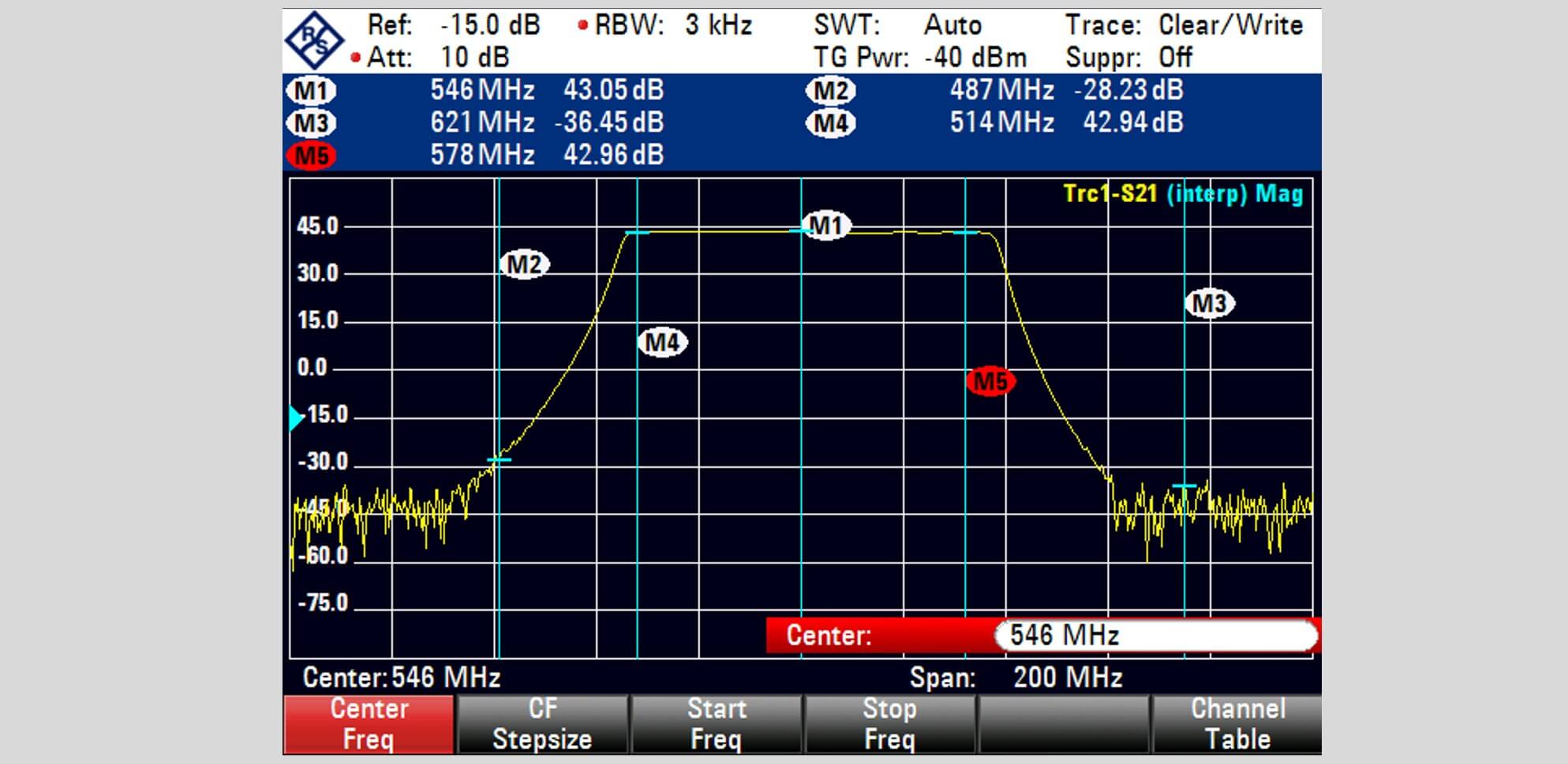
Frequency Response Plot
The receiver has a gain of about 43dB in the passband. Out-of-band rejection is better than 71dB
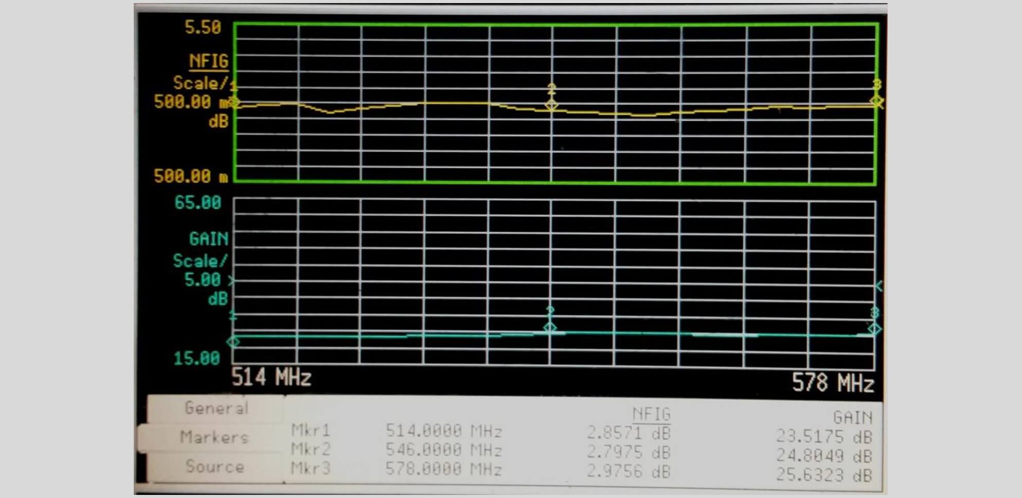
Noise Figure Performance
Noise Figure for this channel is less than 3dB (note: an attenuator had been added after the receiver output to reduce the gain to avoid saturating the noise figure sensor)
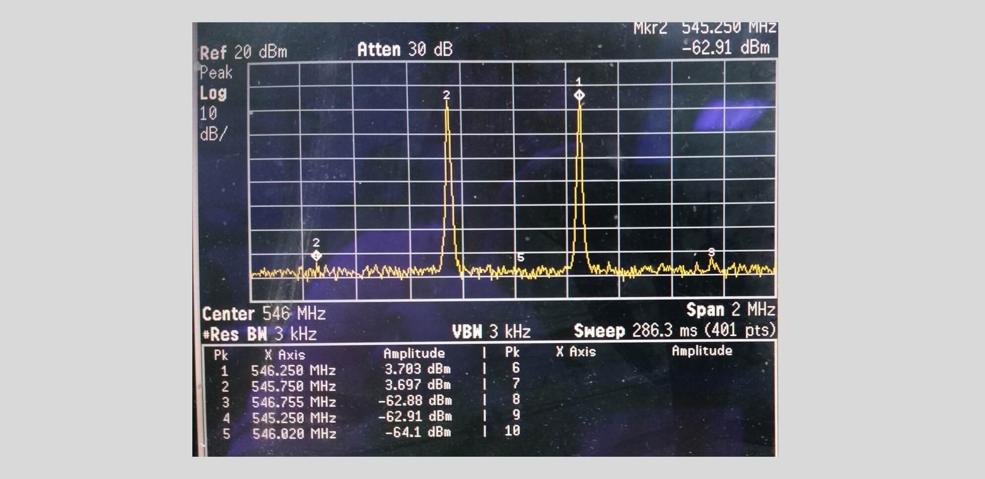
Two-Tone Third Order Intermodulation Products
OIP3 is calculated from the measurement of IM3 as follows:
OIP3 = Pout (single tone) +IM3/2 = 3.7 + (3.7+62.9)/2
Hence OIP3 =+37dBm.
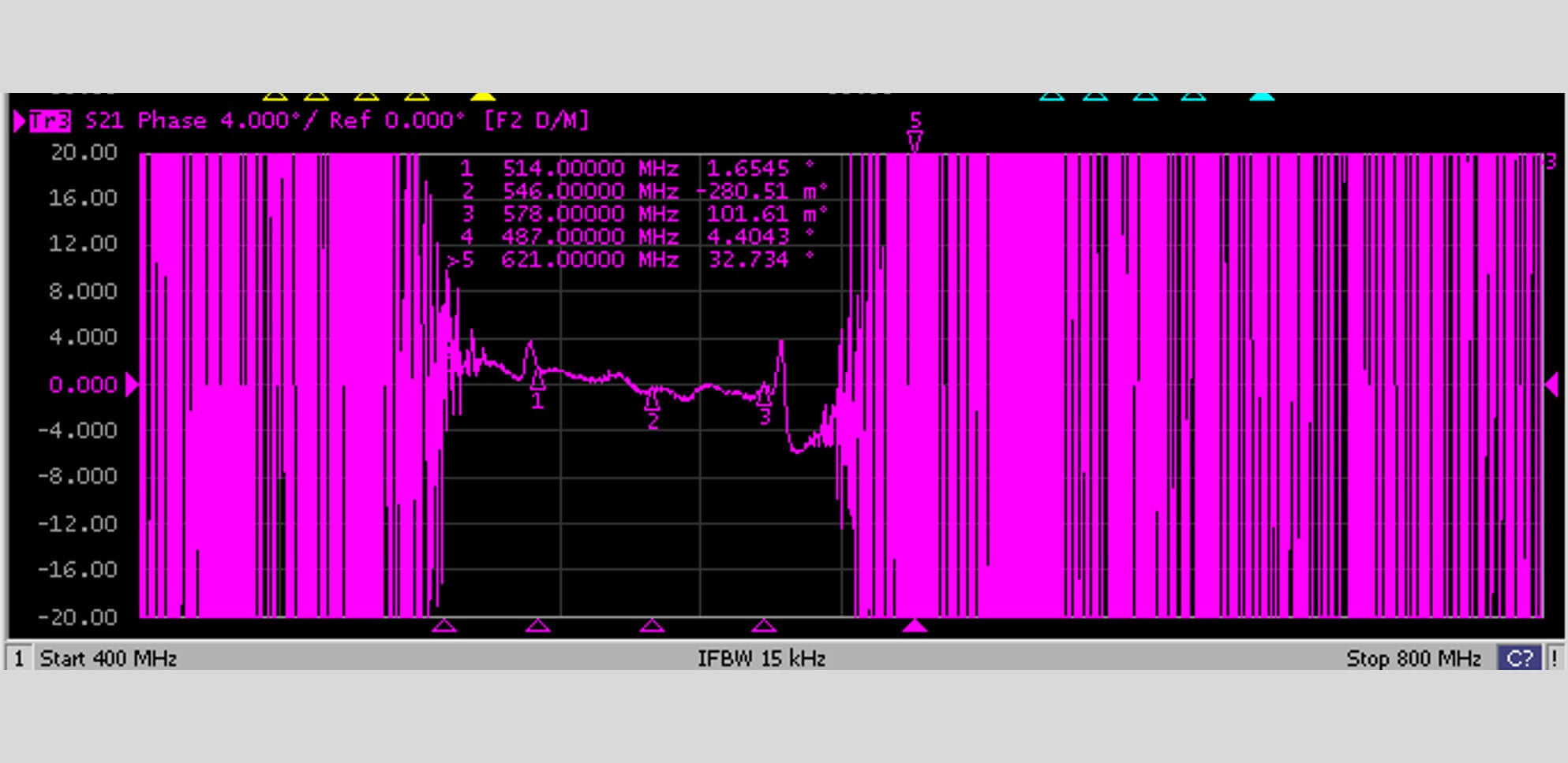
Phase Matching Performance
We measured phase match performance using one of the channels as a reference and compute the difference in phase across the passband frequency.
The phase match for this channel is 4.4 degrees.
Engineering Outcome
This project demonstrates AWG Tech's practical experience in developing multi-band RF receiver modules where repeatability and channel-to-channel consistency are essential.
Beyond integrating RF components, the work required careful filter tuning, system-level optimisation and comparative VNA measurements to achieve the required performance.
The modules were developed for an airborne application. Formal environmental qualification testing was not performed as part of this project, and no environmental certification is claimed.
Need a custom RF module built for your application?
Whether you need a switched filter bank, multi-channel receiver, RF switching assembly or integrated microwave module, AWG Tech can help evaluate your requirements and develop a practical engineering solution.